Help for the correct setting of the magneto
IMPORTAT NOTE ON RELIABILITY
This site was established and published as assistance. It contains subjective opinions and does not serve as a manual for actions resulted from it. The author does not take over any guarantee for the topicality, the correctness, completeness or quality of the information made available. All offers are non-binding and non-committal.
The author reserves the right to change parts of the site or the entire offer without separate notice. Additionally supplements, deletions, the occasional publication or complete termination of the site remain in the right of the author.
In general
This description is meant to be informative for technical personal of FBO’s. It is not meant to replace otherwise descriptions of the aircraft- or engine manufacturer.
Legally binding are the instructions of the aircraft manufacturer, if there is no data, use the instructions of the engine manufacturer.
The detachment and attachment should only be carried out by authorized personal.
Following the de- and attaching of a Slick magneto (models 4200/4300) will be described on a Lycoming engine.
General information
Magnetos come with impulse coupling or drive. Pinion gears are not scope of the delivery. They are delivered by the engine manufacturer, usually they are reused after inspection / overhaul.
Simple put an engine does have a right and a left magneto – motor gliders are the exception as they only have one magneto circuit.
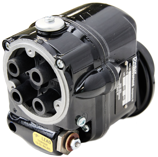
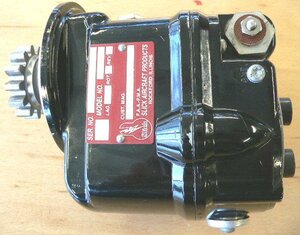
The name plate tells you the type, the year of manufacture (part of the serial number), the rotating direction, the revision, and if applicable the angle of the retard contact points.
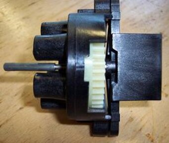
Graphical Representation
right magneto
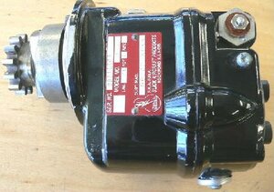
left magneto
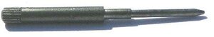
- insert completely
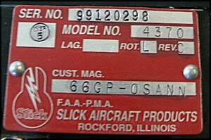
Magneto Type 4370
- SN: built in 1999 in December, sequential . Nr. 298
- Lycoming PN: 66GP-0SANN
- Rotation: L = left
- Revision C
- Ignition timing to engine (Lag.): –
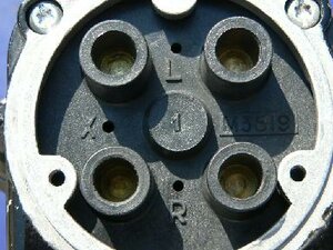
Magneto Type 4370
- X: hole for Lasar magnetos
- R: hole for right turning magnetos
- L: hole for left turning magnetos
Detachment
- Detach all harness cables from the spark plugs
- Detach ground cable from magnetoAttention As soon as the ground cable is detached the ignition lick is also disabled. That leads to a HOT magneto, the engine could start. Make sure that you detach the harness cables first!
- Detach harness plate from magneto
- Detach magneto from engine.
- Attention: For some engines the magneto drive is attached with a separate pinion gear that includes cushions. These cushions could get lost while detaching. Watch that they don’t fall into the engine.
Preparation
Before Installing
- Identify the rotation of the magneto
- Insert timing pin in distributor blocks hole (in this example L) and check with light pressure the point where it moves in. There is only one position per turn.
- Turn the magneto against the rotation direction (turn right) until the timing pin moves in.
Attention If the distributor gear stops while turning into position you need to take it out for around 10mm (to get over the high tension lead) and go on - The engine needs to be timed to the upper death point of cylinder 1. That´s the timing for attaching the magneto
- The gasket can be put with a bit of grease onto the flange in front of attaching the magneto
- The magneto can be attached
Preparation of the engine
The magneto can be attached when the ignition timing of cylinder 1 is correct (see above)
- Remove lower spark plug at cylinder 1
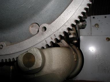
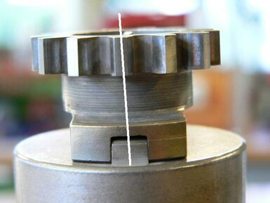
- Turn the engine until cylinder 1 reaches the ignition position (check the positioning of the gear rim). The following picture shows a gear rim with 25° positioning (in front the upper death point). Attention the positioning angle is depending on engine type. It can be found on its data plate.
Note
To check if the engine is timed correct, many mechanics make a leak test at the spark plug hole of cylinder 1. It’s quite small and you can feel with a finger the compressing of the air.
Attaching
After preparation of magneto & engine the magneto will be attached to it.
- Usually the magneto with the impulse coupling comes on the left engine side (flight direction)
- The magneto without impulse coupling will be attached right
- Attach the magnetos with inserted timing pin to the engine and turn them towards the engine rotation direction approx. 10mm
- Tighten the mounting nuts until the magneto can only turn with medium force
- Detach the timing pin
- Set the ignition point
- Ignition point can be taken from engine nameplate
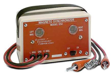
- Attach the test equipment like described by manufacturer
- Turn the engine against normal rotation approx. 30 degree, the impulse coupling should click into place. Turn engine into normal rotation until you hear the impulse coupling snatch. Now return to the position of 10mm before the upper death point.
- Turn on the test equipment and rotate both magnetos until the lamps go on.
- Tighten the mounting nuts more
- Check your timing again. Turn the engine against the rotation way for approx. 10mm and back. The lights should be synch and go on at exactly 30 degree!
- If not, correct the positioning of the magnetos
- Tighten the mounting nuts with specified torque.
- Check again the synch and positioning of the magnetos
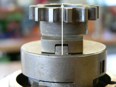
Maybe you can´t position a magneto at the right timing. Check if it does have a pinion gear. If it does have, turn the gear 180 degree. This will lead to half a tooth difference – most times enough to make an exact timing!
After the timing is made we recommend to put a colored marking between magneto and flange. Later checks: If you find the timing differ for more than 3 degree from this initial position you should detach it and send it in for maintenance.
- Attach ground cable / ignition switch cable to the magneto
- Install spark plugs
- Attach the harness
- And finally make a test run
Test run
Run the engine only for a short period of time. The cylinders can get too hot because the air doesn’t flow between them.
Running the engine without cowling can damage it!
Only a complete mounted cowling supplies enough cooling!
Periodic inspection (see FAQ)
Inspection of Slick magnetos 4200/4300/6200 & 6300 series
SB2-80C defines that magnetos have to be checked every 100h externally and every 500h internally.
We recommend 250h for pressurized magnetos because of the former described ozone problems.
Magneto types 4200 & 6200 also need a 1000h inspection that varies from 500h.
Following SB1-89B all Slick magnetos attached to a single ignition system (motor glider) need to be inspected every 50h externally, and 250h or latest after 24month internally.
Inspection of Bendix magnetos S20/S200/S1200/D3000 & D2000 series: Perform a 500h inspection or – if not reached within 4years – an overhaul.
| Short circuit cable | 13-15IN-LBS | 1,4-1,7 Nm |
Crown nut/gear
| Series 4200/6200 | 120-180IN-LBS | 13,5-20,3 Nm |
| Series 4300/6300 | 120-320IN-LBS | 13,5-36,1 Nm |
If the span doesn’t fit the default speed, detach the nut and washer on an even ground and use an emery cloth for grinding.
| Nut, magneto attachment | 190-220IN-LBS | 21,4-24,85 Nm |
| Series 4300/6300 | 18-28IN-LBS | 2,03-3,16 Nm |
Take speed into account!